MCS-170 Project 6: CPU DataPath - Part II
Project Task
In class, we have expanded our discussion of the Central Processing
Unit (CPU) to include the transferring of data from/to Main Memory and
the interpretation of Machine Instructions by the Control Unit.
In this lab, you will use an expanded version of the basic Knob and
Switch CPU simulator to investigate how these two new capabilities
operate
in a computer. During the lab you will be asked a series of
questions.
Record your answers and turn them in to the instructor at the end of
the lab period.
In Lab
Recall that a CPU carries out its duties by dividing up its work into
a set of
subunits. These subunits consist of:
- The Arithmetic
Logic Unit (ALU) -- a
set of electronic circuits that carries out basic arithmetic operations
such as addition, subtraction, and bit manipulations.
- Registers
-- memory locations that are built right on the CPU chip.
- Control
Unit (CU)
-- A set of circuits that take care of fetching data and instructions
from memory, as well as controlling the flow of data back and forth
between the registers and ALU.
So far, you have acted as the Control Unit for the CPU simulator,
setting data buses,
controlling the flow of data, and setting ALU instructions via
knobs. Now, we will add to our CPU simulator components that
simulate Main Memory, where
data can
be stored and retrieved for calculations in the CPU, and an automated Control Unit which will interpret Machine Instructions. Our
control unit will utilize two new components that are critical to
controlling program flow:
- Program
Counter (PC) --
place where the CU stores the memory address of the next instruction to
be executed
- Instruction
Register (IR) --
register to hold the current instruction of the CU
All machine instructions are stored in
Main Memory, and we will assume that the first instruction to be
executed is stored at address 0. Thus, the PC is initially set to 0.
When the CU starts its execution, it reads the PC, grabs the
instruction at that address, decodes the instruction, executes the
instruction, and increments the PC by 1. Then, the CU starts this cycle
all over again. This cycle is called the
Fetch-Execute
cycle of the CU.
Fetch-Execute
Cycle:
initialize PC = 0;
fetch instruction stored at memory location PC and store it in the IR;
set PC = PC + 1;
while (instuction is not HALT) {
     decode the instruction;
     configure the CPU hardware to match the settings indicated in the instruction;
     execute the CPU datapath cycle using those settings;
     when the cycle is complete, fetch next instruction from memory location PC;
     set PC = PC + 1;
}
In order to better understand how the Control Unit carries out this
work, we will use an augmented version of our CPU simulator. The
simulator will again have 4
registers and an
ALU (with operations for addition, subtraction, bitwise-AND, and
bitwise-OR), just as it did before. But, it will also have a
section of Main Memory, consisting of 32 locations, and a Control Unit.
Open a second browser window and in this window go to the
simulator at this site --
http://www.prenhall.com/reed/Chapter14/machine.html
You will see a page with the simulator as shown.
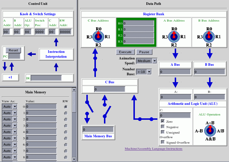
Note that the right-hand section of this
simulator is the same as our old simulator. On the left we have two
new sections labeled "Control Unit"
and "Main Memory.'
To use the simulator, we store instructions and data in Main Memory.
EXERCISE 1:
Copy the following instructions into memory locations 0-7. Make sure
each of the memory locations has the "View As" listbox set to "2" for
binary instructions.
Then, click the "Reset" button for the PC (this sets the PC to 0) and
click "Execute" to start the Fetch-Execute cycle for the CU. The
simulator
will slowly show how instructions are fetched from memory to the IR,
how instructions are decoded (watch how registers and buses are set and
the ALU is set) and how each instruction controls the datapath of the
CPU. Closely watch how each instruction is
executed before moving on, so that you understand what the simulator is
showing. Record the setting of the textboxes in the Control Unit after
the program halts.
Memory Address
Machine Instruction     Action
0:
1000000100000101        // R0 =
M[5]; load memory location 5 into R0
1:
1000000100100110
// R1 = M[6]; load memory location 6 into R1
2:
1010000100100001
// R2 = R0 + R1; add R0 and R1, store in R2
3:
1000001001000111
// M[7] = R2; copy R2 to memory location 7
4:
1111111111111111
// HALT
5:
0000000000001001
// 9; data to be added
6:
0000000000000001
// 1; data to be added
7:
0000000000000000
// location where sum is to be stored
Note that the Control Unit, when decoding an instruction, controls the
ALU, and the set of four switches that go into or out of
the C bus, by the use of a numerical code. The Control Unit sets the
ALU operation by the code: 00=A+B,
01=A|B, 10-A&B, 11=A-B. The four switches are encoded by a
4-bit
number, with each bit encoding a closed switch by 1 and an open
switch by 0. The switches are represented as a 4-bit number
ABCD, where
A= Switch from C Bus to registers
B= Switch from C Bus to Main Memory Bus
C= Switch from Main Memory Bus to C Bus
D= Switch from ALU to C Bus
Refer to Fig. 14.13 on page 261 of the text. The Switch Position in the
CU is set to 1010. Note how the four switches are set corresponding to
this
4-digit number.
EXERCISE 2:
How would the switches be set if the Switch Position Box in the CU is
equal
to 0111?
The set of binary instructions for a particular computer is known
as its Machine Language. The extended simulator we are using
allows for up to 5 different Machine Language instructions to be
entered directly into memory (The five listed on your Instruction Set
handout). The bit patterns in the
machine instructions correspond to the knob and switch settings in the
CPU as described above.
EXERCISE 3: What
sequence of machine-language instructions would cause the
simulator to subtract the contents of memory location 10 from 11 and
store the result in memory location 12? (It's easiest to do this by
writing down the set of instructions in Pseudo-code and then
translating each instruction to its Machine Language form.)
Machine Language programming can be
extremely tedious and error-prone. Mistyping a single bit in an
instruction can have dire consequences in the program's execution. To
reduce the likelihood of errors, assembly languages were developed that
replaced binary numbers
with words and decimal numbers. Our simulator allows for assembly
language
instructions which are then translated into to their equivalent
machine language instructions. For example, the instruction for
loading the contents of Main Memory cell 13 into Register R2 is
"LOAD R2 13" as opposed to the cryptic machine language
instruction "1000000000101101"
(print out the
assembly language instruction set so that you have it handy) .
Assembly language instructions can be stored in our simulator's
Main Memory along
with data.
EXERCISE 4: Suppose
the contents of Main Memory were set as follows:
0: LOAD R0 5
1: LOAD R1 6
2: SUB R2 R1 R0
3: STORE 7 R2
4: HALT
5: 10
6: 5
7: 0
Type these into the simulator, reset the PC, and click "Execute." What
is the end result of running this program?
EXERCISE 5: What is the
sequence of
assembly-language instructions that cause the
simulator to subtract the contents of memory location 10 from 11 and
store the result in memory location 12? (Same problem as Exercise 3)
Type these instructions into
the memory locations of the simulator (starting at address 0), reset
the PC, and then click "Execute." Make sure the program actually
carries out it's intended function.
EXERCISE 6: Write a sequence of
assembly-language instructions that multiplies the contents of memory
location 10 by four and stores the result in memory location 15. For
example, if the number 20 was stored in memory location 10, then your
instructions should result in the number 80 being stored in memory
location 15.
Project Report:
Hand in your answers to the exercises above.
Back to
MCS
170
home page